Routing & Routing Protocols
Objective:
Configure a small network with static routes using the given topology. After configuring two routes on the network, we were to configure RIP. Upon finishing the steps, the instructor introduced a few faults in our network, it was our job to troubleshoot and fix the issues.
Equipment List:
-2x Computer
-2x Router
-2x Switch
-2x Ethernet Cable
-Hyperterminal
Notes and Observations:
We began by configuring “pc1” and “router1” with the following values:
IP: 192.168.14.2
Subent Mask: 255.255.255.0
Gateway: 192.168.14.1
Router e0 IP: 192.168.14.1
Router f0 IP: 192.168.15.1
Then, “pc2” and “router2” with the following:
IP: 192.168.16.2
Subent Mask: 255.255.255.0
Gateway: 192.168.16.1
Router e0 IP: 192.168.16.1
Router f0 IP: 192.168.15.2
After testing the network and routes, we proceeded to route from router1 to router2 via the 15.1 interface. In addition, router2 to router1 via the 15.2 interface. Soon after testing the new routes, it was time to configure the RIP. Each of the two routers were assigned new IP addresses in their e0/f0 interfaces. Starting with router1, 172.16.0.1, and 172.17.0.1, then moving onto router2. The second router consisted of 172.18.0.1, and 172.17.0.2
After ensuring that routing updates were being sent, it was time for our troubleshooting. Upon leaving the classroom, the professor created multiple faults in our network, in which we were to troubleshoot and fix. We pretty immediately gathered that one of our network cables were unplugged, the other took some testing. Our network was down, but not in its entirety. After pinging back and forth, we were able to isolate the source, the IP, Subnet, and Gateway of pc2 was obstructed. After fixing the issues, everything was a-go.
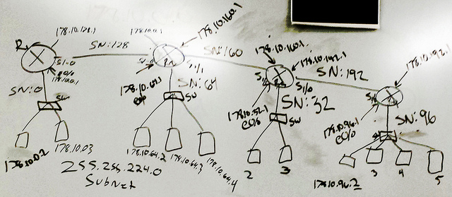
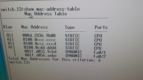
Diagrams, Flowcharts, and Figures:

– Figure 1
References:
N/A
Questions:
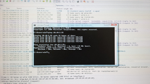
1.) What method did you use to test connectivity? Was it successful? If not, why did the test fail?
– Ping, route trace. There were a few time when this was not successful, from routers that were restarting on their own, to issues with our PC network settings.
2.) Why do you need static routes on both routers? Why does the route information include the IP address of the other router?
-Because a static route is “hard coded” and each path is specifically specified by the network admin. Static was the best choice for a network as small as the one we created. It would not be optimal in a larger or more complicated network though.
3.) Was there any output from the debug command?
-yes
4.) What did the output show?
-Various updates
5.) Describe the process it took to isolate the fault and the actions necessary to correct the problems.
– Ping the other computer and routers
– Check cables
– Check network/router IP, Subnet, Gateway
Conclusions:


